

 This blog provides high availability (HA) guidelines using group replication architecture and deployment recommendations in MySQL, based on our best practices.
Every architecture and deployment depends on the customer requirements and application demands for high availability and the estimated level of usage. For example, using high read or high write applications, or both, with a need for 99.999% availability.
Here, we give architecture and deployment recommendations along with a technical overview for a solution that provides a high level of high availability and assumes the usage of high read/write applications (20k or more queries per second).
Layout
Components
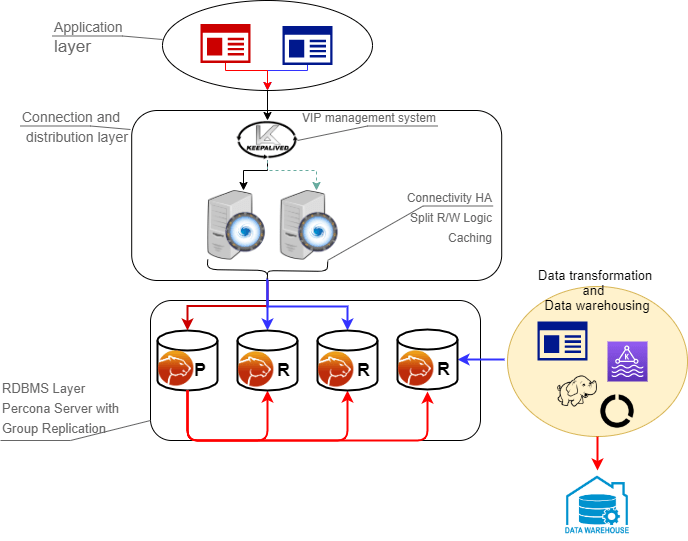
This architecture is composed of two main layers:
- Connection and distribution layer
- RDBMS (Relational Database Management System) layer
Connection Layer
The connection layer is composed of:
- Application to proxy redirection mechanism which can be anything from a Virtual IP managed by Keepalived local service to a DNS resolution service like Amazon Route 53. Its function is to redirect the traffic to the active Proxy node.
- Proxy connection distribution is composed of two or more nodes. Its role is to redirect the traffic to the active nodes of the Group Replication cluster. In cases like ProxySQL where the proxy is a level 7 proxy and is able to perform Read/Write split, this layer is also in charge of redirecting writes to the Primary node and reads to the Replicas, and of HA to prevent a single point of failure
Data Layer
The data layer is composed of:
- Primary node serving writes (or source) – this is the node that will accept writes and DDL modifications. Data will be processed following the ACID paradigm (atomicity, consistency, isolation, durability) and replicated to all other nodes.
- Replica nodes are the elements serving read requests. Some replica nodes can be elected Primary in case of Primary node failure. A replica node should be able to leave and join back a healthy cluster without impacting the service.
- Replication mechanism to distribute changes across nodes and in this solution is done with Group Replication. Group Replication is a tightly coupled solution which means that the database cluster is based on a Datacentric approach (single state of the data, distributed commit). In this case, the data is consistent in time across nodes and replication requires a high performant link. Given that, geographic distribution is strongly discouraged and Disaster Recovery (DR) is not implicitly supported by the main Group Replication mechanism.
The node characteristics (CPU/RAM/Storage) are not relevant to the main solution design. They instead must reflect the estimated workload the solution will have to cover, which is a case-by-case identification.
What is important to keep in mind is that all nodes that are part of the cluster must have the same characteristics. If they don’t, the cluster will be imbalanced and service will be affected.
As a generic indication, we recommend using solutions with at least 8 cores and 16GB RAM when production.
High Availability
How do we measure availability and at what point does it become “high” availability?
Generally speaking, the measurement of availability is done by establishing a measurement time frame and dividing it by the time that it was available. This ratio will rarely be 1, which is equal to 100% availability. At Percona we don’t consider a solution to be highly available if it is not at least 99% or “two nines” available.
| Availability % | Downtime per year | Downtime per month | Downtime per week | Downtime per day |
| 99% (“two nines”) | 3.65 days | 7.31 hours | 1.68 hours | 14.40 minutes |
| 99.5% (“two nines five”) | 1.83 days | 3.65 hours | 50.40 minutes | 7.20 minutes |
| 99.9% (“three nines”) | 8.77 hours | 43.83 minutes | 10.08 minutes | 1.44 minutes |
| 99.95% (“three nines five”) | 4.38 hours | 21.92 minutes | 5.04 minutes | 43.20 seconds |
| 99.99% (“four nines”) | 52.60 minutes | 4.38 minutes | 1.01 minutes | 8.64 seconds |
| 99.995% (“four nines five”) | 26.30 minutes | 2.19 minutes | 30.24 seconds | 4.32 seconds |
| 99.999% (“five nines”) | 5.26 minutes | 26.30 seconds | 6.05 seconds | 864.00 milliseconds |
How is High Availability Achieved?
There are three key components to high availability:
- Infrastructure – This is the physical or virtual hardware that database systems rely on to run. Without enough infrastructure (VM’s, networking, etc) there cannot be high availability. The easiest example is: there is no way to make a single server highly available.
- Topology Management – This is the software management related specifically to the database and managing its ability to stay consistent in the event of a failure. Many clustering or synchronous replication solutions offer this capability out of the box. However, for asynchronous replication, this is handled by additional software.
- Connection Management – This is the software management related specifically to the networking and connectivity aspect of the database. Clustering solutions typically bundle with a connection manager, however in asynchronous clusters deploying a connection manager is mandatory for high availability.
This Solution Provides:
The proposed solution, based on a tightly coupled database cluster, offers an HA level of 99.995% when coupled with the Group replication setting group_replication_consistency=AFTER.

Failovers
If properly planned and architected, a database failure or configuration change that requires a restart shouldn’t affect the stability of the database infrastructure. Failovers are an integral part of a stability strategy and aligning the business requirements for availability and uptime with failover methodologies is critical to achieving those goals. Below are the 3 main types of failovers that can occur in database environments.
- Planned Failover: A planned failover is a failover that has been scheduled in advance or occurs at a regular interval. There can be many reasons for planned failovers including patching, large data operations, retiring existing infrastructure, or simply testing the failover strategy.
- Unplanned Failover: An unplanned failover is what occurs when a database unexpectedly becomes unresponsive or experiences instability. This could also include emergency changes that do not fall under the planned failover cadence or scheduling parameters. Unplanned failovers are generally considered higher-risk operations due to the high stress and high potential for either data corruption or data fragmentation.
- Regional or Disaster Recovery Failover: Unplanned failovers still work with the assumption that additional database infrastructure is immediately available and in a usable state. In a regional or DR failover, we would be making the assumption that there is a large-scale infrastructure outage that requires the business to move its operations away from its current availability zone.
- This solution covers both planned and unplanned failovers.
Maintenance Windows
Major vs Minor Maintenance: Although it may not be obvious at first, not all maintenance activities are created equal and do not have the same dependencies. It is good to separate maintenance that demands downtime or failover from maintenance that can be done without impacting those important stability metrics. When defining these maintenance dependencies there can be a change in the actual maintenance process that allows for a different cadence.
Maintenance Without Service Interruption: With rolling restart and using proper version upgrade it is possible to cover both major and minor maintenance without service interruption.
Uptime
When referring to database stability, uptime is likely the largest indicator of stability and oftentimes is the most obvious symptom of an unstable database environment. Uptime is composed of 3 key components and, contrary to common perception, is based on what happens when the database software is not able to take incoming requests rather than maintaining the ability to take requests with errors.
Recovery Time Objective (RTO): This can be boiled down to a very simple question “How long can the business sustain a database outage?”. Once the business is aligned with a goal of a minimum viable recovery time objective, it is much more straightforward to plan and invest in the infrastructure required to meet that requirement. It is important to acknowledge that while everyone desires 100% uptime, there is a need for realistic expectations that align with the business needs and not a technical desire.
Recovery Point Objective (RPO): There is a big distinction between the Recovery Point and the Recovery Time for database infrastructure. The database can be available, but not to the exact state that it was when it became unavailable. That is where Recovery Point comes in. The question we ask here is “How much data can the business lose during a database outage?”. All businesses have their own requirements here and it is worthy to note that it is always the goal to never sustain any data loss. But this is framed in a worst-case scenario how much data could be lost and the business maintains the ability to continue.
Disaster Recovery: While RTO and RPO are great for unplanned outages or small-scale hiccups to the infrastructure, when we talk about Disaster Recovery this is a major large-scale outage not strictly for the database infrastructure. How capable is the business of restarting operations with the assumption that all resources are completely unavailable in the main availability zone? The assumption here is that there is no viable restoration point or time that aligns with the business requirements. While each DR scenario is unique based on available infrastructure, backup strategy, and technology stack, there are some common threads for any scenario.
This solution helps improve uptime:
Using this solution will help you to significantly reduce both RPO and RTO. Given the tightly coupled cluster solution approach, the failure of a single node will not result in service interruption.
Increasing the number of nodes will also improve the cluster resilience by the formula:
F = (N -1) / 2
Where:
F – Number of admissible failures
N – number of nodes in the cluster
Examples:
In a cluster of 5 nodes, F = (5 – 1)/2 = 2.
The cluster can support up to 2 failures.
In a cluster of 4 nodes, F = (4 – 1)/2 = 1.
The cluster can support up to 1 failure.
This solution also allows for a more restrictive backup policy, dedicating a node to the backup cycle, which will help in keeping RPO low. As previously mentioned, DR is not covered by default by the solution which will require an additional replication setup and controller.
Measurement and Monitoring
To ensure database infrastructure is performing as intended or at its best, it is necessary to measure specific metrics and alert when some of these metrics are not in line with expectations. Periodic review of these measurements is also encouraged to promote stability and understand potential risks associated with the database infrastructure. Below are the 3 aspects of Database performance measurement and monitoring
Measurement: To understand how a database infrastructure is performing there is a need to measure multiple aspects of the infrastructure. With measurement, it’s important to understand the impact of the sample sizes, sample timing, and sample types.
Metrics: Metrics refer to the actual parts of the database infrastructure being measured. When we discuss metrics, more isn’t always better as it could introduce unintentional noise or allow for troubleshooting to become overly burdensome.
Alerting: When one or many metrics of the database infrastructure is not within a normal or acceptable range, an alert should be generated so that the team responsible for the appropriate portion of the database infrastructure can investigate and remedy it
Monitoring for this solution is covered by:
Percona Monitoring and Management has a specific dashboard to monitor the Group Replication state and cluster status as a whole. (https://www.percona.com/doc/percona-monitoring-and-management/2.x/introduction.html) has a specific dashboard to monitor Group Replication state, and cluster status as a whole.
How to Implement the Infrastructure
In this section, we are providing the step by step instructions on how to implement the above solution.
The Elements
The following will be used:
- 1 Virtual IP for ProxySQL failover – 192.168.4.194
- 2 ProxySQL nodes
- Proxy1 192.168.4.191
- Proxy2 192.168.4.192
- 4 MySQL nodes in Single Primary mode
- Gr1 192.168.4.81 – Initial Primary
- Gr2 192.168.4.82 – Replica / failover
- Gr3 192.168.4.83 – Replica / failover
- Gr4 192.168.4.84 – Replica / Backup
- Ports. All ports must be open if a firewall is in place or any other restriction like AppArmor or SELinux.
- Proxysql
- 6033
- 6032
- 3306
- MySQL – GR
- 3306
- 33060
- 33061
- Proxysql
Software Installation
First, you need to install the Percona Distribution for MySQL, the Percona Server for MySQL-based variant, on each node. Follow the instructions here to install Percona Server for MySQL v8.0.
Configure the Nodes
Before anything, make sure that all the nodes use the same time-zone and time:
1 2 | [root@gr1 ps8]# date Tue Aug 18 08:22:12 EDT 2020 |
Check also for ntpd service to be present and enabled. Be sure that each node resolves the other nodes by name:
1 | root@gr1 ps8]# for i in 1 2 3 4 ; do ping -c 1 gr$i > /dev/null;echo $?; done |
If not able to resolve, add the entries in the /etc/hosts file.
Once instances are up and running check the Percona Server for MySQL version on each node:
1 2 3 | (root@node1) [(none)]>s -------------- /opt/mysql_templates/PS-8P/bin/mysql Ver 8.0.20-11 for Linux on x86_64 (Percona Server (GPL), Release 11, Revision 159f0eb) |
Step 1
Create a proper user for administration:
1 2 3 4 5 | CREATE user dba@localhost identified by 'dbapw'; CREATE user dba@'192.168.%' identified by 'dbapw'; GRANT ALL on *.* to dba@localhost with grant option; GRANT ALL on *.* to dba@'192.168.%' with grant option; |
Exit from the client as user root and login as user dba.
Be sure to have a good and unique SERVER_ID value:
1 2 3 4 5 6 7 | (dba@node1) [(none)]>show global variables like 'server_id'; +---------------+-------+ | Variable_name | Value | +---------------+-------+ | server_id | 1 | <--- Not good given the same for all nodes +---------------+-------+ 1 row in set (0.01 sec) |
It’s now time to add group replication settings to the instances.
Step 2
Stop all running nodes, then in the my.cnf add:
1 2 3 4 5 6 7 8 9 10 11 12 13 14 15 16 17 18 19 20 21 22 23 24 25 26 27 28 29 30 31 32 33 34 35 36 37 38 39 40 41 42 43 44 | ##################### #Replication + binlog settings ##################### auto-increment-increment =1 auto-increment-offset =1 log-bin =<path_to_logs>/binlog log-bin-index =binlog.index binlog-checksum =NONE binlog-format =ROW binlog-row-image =FULL log-slave-updates =1 binlog-transaction-dependency-tracking =WRITESET enforce-gtid-consistency =TRUE gtid-mode =ON master-info-file =master.info master-info-repository =TABLE relay_log_info_repository =TABLE relay-log =<path_to_logs>/relay sync-binlog =1 ### SLAVE SECTION skip-slave-start slave-parallel-type = LOGICAL_CLOCK slave-parallel-workers = 4 slave-preserve-commit-order = 1 ###################################### #Group Replication ###################################### plugin_load_add ='group_replication.so' plugin-load-add ='mysql_clone.so' group_replication_group_name ="aaaaaaaa-aaaa-aaaa-aaaa-aaaaaaaaaaaa" <-- Not good use something that will help you to identify the GR transactions and from where they come from IE "dc1euz1-aaaa-aaaa-aaaa-aaaaaaaaaaaa" group_replication_start_on_boot =off group_replication_local_address = "192.168.4.81/2/3/4:33061" <---- CHANGE THIS TO MATCH EACH NODE LOCAL IP group_replication_group_seeds = "192.168.4.81:33061,192.168.4.82:33061,192.168.4.83:33061,192.168.4.84:33061" group_replication_bootstrap_group = off transaction-write-set-extraction = XXHASH64 |
Restart all nodes and connect to them.
Step 3
Create a user for replication (on all nodes):
1 2 3 4 5 | SET SQL_LOG_BIN=0; CREATE USER replica@'192.168.4.%' IDENTIFIED BY 'replicapw'; #<--- Please note the filter by IP is more restrictive GRANT REPLICATION SLAVE ON *.* TO replica@'192.168.4.%'; FLUSH PRIVILEGES; SET SQL_LOG_BIN=1; |
Link the nodes with replication channel (on all nodes):
1 | CHANGE MASTER TO MASTER_USER='replica', MASTER_PASSWORD='replicapw' FOR CHANNEL 'group_replication_recovery'; |
Check the current status:
1 2 3 4 5 6 7 8 9 10 11 12 13 14 15 16 17 18 19 20 21 22 23 24 25 26 | (dba@node1) [(none)]>u performance_schema (dba@node1) [performance_schema]>show tables like '%repl%'; +-------------------------------------------+ | Tables_in_performance_schema (%repl%) | +-------------------------------------------+ | replication_applier_configuration | | replication_applier_filters | | replication_applier_global_filters | | replication_applier_status | | replication_applier_status_by_coordinator | | replication_applier_status_by_worker | | replication_connection_configuration | | replication_connection_status | | replication_group_member_stats | | replication_group_members | <------------------------ +-------------------------------------------+ (dba@node1) [performance_schema]>select * from replication_group_membersG CHANNEL_NAME: group_replication_applier MEMBER_ID: MEMBER_HOST: MEMBER_PORT: MEMBER_STATE: MEMBER_ROLE: OFFLINE MEMBER_VERSION: 1 row in set (0.00 sec) |
At this stage, you should be able to start the first (Primary) cluster node.
Only on GR1:
1 2 3 | (dba@node1)[none]> SET GLOBAL group_replication_bootstrap_group=ON; (dba@node1)[none]> START GROUP_REPLICATION; (dba@node1)[none]> SET GLOBAL group_replication_bootstrap_group=OFF; |
And then check it:
1 2 3 4 5 6 7 8 | (dba@node1) [none]>select * from performance_schema.replication_group_membersG CHANNEL_NAME: group_replication_applier MEMBER_ID: 90a353b8-e6dc-11ea-98fa-08002734ed50 MEMBER_HOST: gr1 MEMBER_PORT: 3306 MEMBER_STATE: ONLINE MEMBER_ROLE: PRIMARY MEMBER_VERSION: 8.0.20 |
Once the Primary is running, connect on the second node GR2 and start Group replication:
1 2 | (dba@node2) [none]>START GROUP_REPLICATION; Query OK, 0 rows affected (4.60 sec) |
Check if it registered correctly:
1 2 3 4 5 6 7 8 9 10 11 12 13 14 15 16 17 | (dba@node2) [performance_schema]>select * from replication_group_membersG *************************** 1. row *************************** CHANNEL_NAME: group_replication_applier MEMBER_ID: 58ffd118-e6dc-11ea-8af8-08002734ed50 MEMBER_HOST: gr2 MEMBER_PORT: 3306 MEMBER_STATE: ONLINE MEMBER_ROLE: SECONDARY MEMBER_VERSION: 8.0.20 *************************** 2. row *************************** CHANNEL_NAME: group_replication_applier MEMBER_ID: 90a353b8-e6dc-11ea-98fa-08002734ed50 MEMBER_HOST: gr1 MEMBER_PORT: 3306 MEMBER_STATE: ONLINE MEMBER_ROLE: PRIMARY MEMBER_VERSION: 8.0.20 |
Test if replication works:
On GR1
1 2 3 4 5 6 7 8 9 10 11 | (dba@node1) [performance_schema]>create schema test; Query OK, 1 row affected (0.76 sec) (dba@node1) [performance_schema]>u test Database changed (dba@node1) [test]>create table test1 (`id` int auto_increment primary key); Query OK, 0 rows affected (0.32 sec) (dba@node1) [test]>insert into test1 values(null); Query OK, 1 row affected (0.34 sec) |
On GR2
1 2 3 4 5 6 7 8 9 | (dba@node2) [performance_schema]>use test Database changed (dba@node2) [test]>select * from test1; +----+ | id | +----+ | 1 | +----+ 1 row in set (0.00 sec) |
Start group replication of the other two nodes GR3 and GR4:
1 2 | (dba@node3) [performance_schema]>START GROUP_REPLICATION; (dba@node4) [performance_schema]>START GROUP_REPLICATION; |
Proxy Setup
Step 1
In our solution we will use two ProxySQL nodes:
- Proxy1 192.168.4.191
- Proxy2 192.168.4.192
First, you need to install ProxySQL on the nodes you have selected, in our case the two above.
To install the software follow the instructions in How to Install ProxySQL From the Percona Repository. Once you have installed the software, we first need to grant access to the ProxySQL monitor user to our Percona Server for MySQL nodes.
Create monitor user in MySQL group replication nodes:
1 2 3 4 | Create monitor user in MySQL group replication nodes: create user monitor@'192.168.4.%' identified by 'monitor'; grant usage on *.* to 'monitor'@'192.168.4.%'; grant select on sys.* to 'monitor'@'192.168.4.%'; |
Then define some basic variables:
1 2 3 4 5 6 7 8 9 10 11 12 13 14 15 16 17 | update global_variables set Variable_Value='admin:admin;cluster1:clusterpass' where Variable_name='admin-admin_credentials'; update global_variables set variable_value='cluster1' where variable_name='admin-cluster_username'; update global_variables set variable_value='clusterpass' where variable_name='admin-cluster_password'; update global_variables set Variable_Value=0 where Variable_name='mysql-hostgroup_manager_verbose'; update global_variables set Variable_Value='true' where Variable_name='mysql-query_digests_normalize_digest_text'; update global_variables set Variable_Value='8.0.20' where Variable_name='mysql-server_version'; update global_variables set Variable_Value='utf8' where Variable_name='mysql-default_charset'; update global_variables set Variable_Value=300 where Variable_name='mysql-tcp_keepalive_time'; update global_variables set Variable_Value='true' where Variable_name='mysql-use_tcp_keepalive'; update global_variables set Variable_Value='true' where Variable_name='mysql-verbose_query_error'; update global_variables set Variable_Value='true' where Variable_name='mysql-show_processlist_extended'; update global_variables set Variable_Value=50000 where Variable_name='mysql-max_stmts_cache'; update global_variables set Variable_Value='false' where Variable_name='admin-web_enabled'; update global_variables set Variable_Value='0' where Variable_name='mysql-set_query_lock_on_hostgroup'; load admin variables to run;save admin variables to disk; load mysql variables to run;save mysql variables to disk; |
The user name and password need to reflect your standards. The ones used above are just an example. Then set up the nodes as a cluster:
1 2 3 | INSERT INTO proxysql_servers (hostname,port,weight,comment) VALUES('192.168.4.191',6032,100,'PRIMARY'); INSERT INTO proxysql_servers (hostname,port,weight,comment) VALUES('192.168.4.192',6032,100,'SECONDARY'); load proxysql servers to run;save proxysql servers to disk; |
Step 2
Define user(s), servers, and query rules to perform read/write split. Create one or more valid user(s), for instance, if you have a user named app_gr with the password test, that has access to your group replication cluster:
1 2 | insert into mysql_users (username,password,active,default_hostgroup,default_schema,transaction_persistent,comment) values ('app_gr','test',1,400,'mysql',1,'application test user GR'); LOAD MYSQL USERS TO RUNTIME;SAVE MYSQL USERS TO DISK; |
Define servers:
1 2 3 4 5 6 | INSERT INTO mysql_servers (hostname,hostgroup_id,port,weight,max_connections,comment) VALUES ('192.168.4.81',400,3306,10000,2000,'GR1'); INSERT INTO mysql_servers (hostname,hostgroup_id,port,weight,max_connections,comment) VALUES ('192.168.4.81',401,3306,100,2000,'GR1'); INSERT INTO mysql_servers (hostname,hostgroup_id,port,weight,max_connections,comment) VALUES ('192.168.4.82',401,3306,10000,2000,'GR2'); INSERT INTO mysql_servers (hostname,hostgroup_id,port,weight,max_connections,comment) VALUES ('192.168.4.83',401,3306,10000,2000,'GR2'); INSERT INTO mysql_servers (hostname,hostgroup_id,port,weight,max_connections,comment) VALUES ('192.168.4.84',401,3306,1,2000,'GR2'); LOAD MYSQL SERVERS TO RUNTIME; SAVE MYSQL SERVERS TO DISK; |
Define query rules to get read-write split:
1 2 3 | INSERT INTO mysql_query_rules (rule_id,proxy_port,username,destination_hostgroup,active,retries,match_digest,apply) values(4040,6033,'app_gr',400,1,3,'^SELECT.*FOR UPDATE',1); INSERT INTO mysql_query_rules (rule_id,proxy_port,username,destination_hostgroup,active,retries,match_digest,multiplex,apply) values(4042,6033,'app_gr',401,1,3,'^SELECT.*$',1,1); LOAD MYSQL QUERY RULES TO RUN;SAVE MYSQL QUERY RULES TO DISK; |
Step 3
Once we have all the configuration ready, we need to have a special view in the SYS schema in our Percona server nodes. The view working for the server version 8 and above can be found here (https://github.com/Percona-Lab/group_replication_tools/blob/master/GR_sys_view_forProxysql_v1.sql)
Run that sql on the PRIMARY node of the Group Replication cluster.
Step 4
Now we are ready to activate the native support for Group Replication in ProxySQL. We will use the following group definition:
Writer HG-> 400
Reader HG-> 401
BackupW HG-> 402
Offline HG-> 9401
1 2 3 | INSERT INTO mysql_group_replication_hostgroups (writer_hostgroup,backup_writer_hostgroup,reader_hostgroup, offline_hostgroup,active,max_writers,writer_is_also_reader,max_transactions_behind) values (400,402,401,9401,1,1,1,100); LOAD MYSQL SERVERS TO RUNTIME; SAVE MYSQL SERVERS TO DISK; |
Few comments here about the parameters (for full reference see here https://proxysql.com/documentation/main-runtime#mysql_group_replication_hostgroups ). We recommend setting the number of writers always to 1, and witer_is_also_reader to 1 as well to obtain the most reliable results.
max_writers: 1
writer_is_also_reader: 1
The max_transactions_behind is a subjective parameter that you should calculate on the basis of your needs. If for instance you cannot have a stale read, it will be safe to set this value to a low number (ie 50) and to set in all Group replication nodes:
1 | set global group_replication_consistency=AFTER; |
If instead, you have no issue or strict requirements about some stale read, you can relax the parameter and ignore the group_replication_consistency setting. Our recommended setting is group_replication_consistency=AFTER and max_transactions_behind: 100.
Proxy HA
The final step is to enable High Availability for the ProxySQL layer. In this approach, we will use the well-known keepalived service. First, install the keepalived software using yum or apt-get on each ProxySQL node:
1 2 3 | Sudo yum install -y keepalived Or Sudo apt-get install -y keepalived |
Then modify the /etc/keepalived/keepalived.conf file accordingly to your setup. In our case:
- Proxy1 192.168.4.0/24 dev enp0s9 proto kernel scope link src 192.168.4.191
- Proxy2 192.168.4.0/24 dev enp0s9 proto kernel scope link src 192.168.4.192
- VIP 192.168.4.194
We want to have the primary to be Proxy1 and the failover node to be Proxy2. Given that the config will look like:
1 2 3 4 5 6 7 8 9 10 11 12 13 14 15 16 17 18 19 20 21 22 23 24 25 26 27 | cat /etc/keepalived/keepalived.conf global_defs { # Keepalived process identifier router_id proxy_HA } # Script used to check if Proxy is running vrrp_script check_proxy { script "killall -0 proxysql" interval 2 weight 2 } # Virtual interface # The priority specifies the order in which the assigned interface to take over in a failover vrrp_instance VI_01 { state MASTER interface enp0s9 virtual_router_id 51 priority 100 <----- This needs to be different for each ProxySQL node, like 100/99 # The virtual ip address shared between the two load balancers virtual_ipaddress { 192.168.4.194 dev enp0s9 } track_script { check_proxy } } |
Once done, start the keepalived service, and from now on the VIP will be associated with the Proxy1 unless service is down.
In the system log:
1 2 3 4 5 6 7 8 9 10 11 12 13 14 15 16 | proxysql1 Keepalived_vrrp[17422]: VRRP sockpool: [ifindex(4), proto(112), unicast(0), fd(10,11)] proxysql1 Keepalived_vrrp[17422]: VRRP_Script(check_proxy) succeeded proxysql1 Keepalived_vrrp[17422]: VRRP_Instance(VI_01) Transition to MASTER STATE proxysql1 Keepalived_vrrp[17422]: VRRP_Instance(VI_01) Received advert with higher priority 101, ours 100 proxysql1 Keepalived_vrrp[17422]: VRRP_Instance(VI_01) Entering BACKUP STATE proxysql1 Keepalived_vrrp[17422]: VRRP_Instance(VI_01) Changing effective priority from 100 to 102 proxysql1 Keepalived_vrrp[17422]: VRRP_Instance(VI_01) forcing a new MASTER election proxysql1 Keepalived_vrrp[17422]: VRRP_Instance(VI_01) Transition to MASTER STATE proxysql1 Keepalived_vrrp[17422]: VRRP_Instance(VI_01) Entering MASTER STATE proxysql1 Keepalived_vrrp[17422]: VRRP_Instance(VI_01) setting protocol VIPs. proxysql1 Keepalived_vrrp[17422]: Sending gratuitous ARP on enp0s9 for 192.168.4.194 proxysql1 Keepalived_vrrp[17422]: VRRP_Instance(VI_01) Sending/queueing gratuitous RPs on enp0s9 for 192.168.4.194 proxysql1 Keepalived_vrrp[17422]: Sending gratuitous ARP on enp0s9 for 192.168.4.194 .. proxysql1 Keepalived_vrrp[17422]: Sending gratuitous ARP on enp0s9 for 192.168.4.194 proxysql1 avahi-daemon[989]: Registering new address record for 192.168.4.194 on enp0s9.IPv4. |
Disaster Recovery Implementation
The implementation of a DR (Disaster Recovery) site will follow the same direction provided for the main site. There are only some generic rules that should be followed:
- A DR site should be located in a different geographic location than the main site (several hundred kilometers/miles away).
- The connection link between the main site and the DR site can only be established using asynchronous replication (standard MySQL replication setup ).
Monitoring
There are few ways to monitor a Group Replication cluster. The easiest way is to have Percona Monitoring and Management (Version 2.10 or later) deployed to do it for you. For an easy installation of Percona Monitoring and Management check out this quickstart.
Percona Monitoring and Management
The only important thing to remember is that when registering the Percona Server for MySQL node or the MySQL node, you should specify the replication_set flag.
1 | Ie: pmm-admin add mysql --username=pmm --password=pmm --query-source=perfschema --replication-set=gr_test_lab group_rep4 127.0.0.1:3306 |
Then you can use the Group replication Dashboard and monitor your cluster with a lot of details.
The sections are:
- Overview(3 panels)
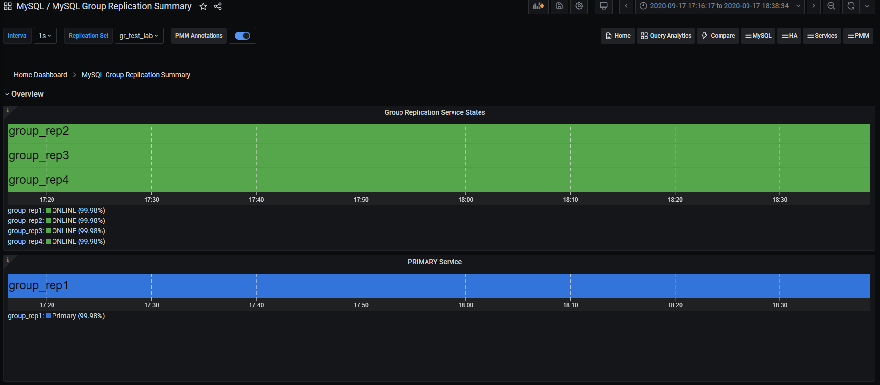
- Replication Delay Details(3 panels)
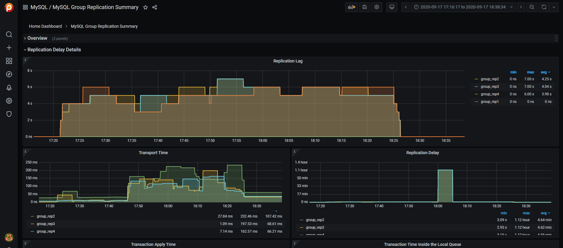
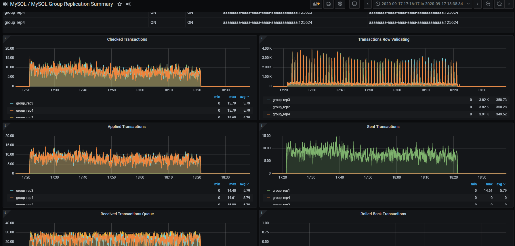
- Transactions(8 panels)
- Conflicts
From Command Line
From the command line you need to manually query the tables in Performance schema:
1 2 3 4 5 6 7 8 9 10 11 12 | +----------------------------------------------+ | replication_applier_configuration | | replication_applier_filters | | replication_applier_global_filters | | replication_applier_status | | replication_applier_status_by_coordinator | | replication_applier_status_by_worker | | replication_connection_configuration | | replication_connection_status | | replication_group_member_stats | | replication_group_members | +----------------------------------------------+ |
For instance, to get the lag in the number of transactions on a node:
1 2 3 4 5 6 7 8 9 10 11 12 13 14 15 16 17 18 19 20 21 | select @last_exec:=SUBSTRING_INDEX(SUBSTRING_INDEX( @@global.GTID_EXECUTED,':',-1),'-',-1) last_executed;select @last_rec:=SUBSTRING_INDEX(SUBSTRING_INDEX(Received_transaction_set,':',-1),'-',-1) last_received FROM performance_schema.replication_connection_status WHERE Channel_name = 'group_replication_applier'; select (@last_rec - @last_exec) as real_lag; +---------------+ | last_executed | +---------------+ | 125624 | +---------------+ 1 row in set, 1 warning (0.03 sec) +---------------+ | last_received | +---------------+ | 125624 | +---------------+ 1 row in set, 1 warning (0.00 sec) +----------+ | real_lag | +----------+ | 0 | +----------+ 1 row in set (0.00 sec) |
Or use a more composite query:
1 2 3 4 5 6 7 8 9 10 11 12 13 14 15 16 17 18 19 20 | SELECT conn_status.channel_name as channel_name, conn_status.service_state as IO_thread, applier_status.service_state as SQL_thread, conn_status.LAST_QUEUED_TRANSACTION as last_queued_transaction, applier_status.LAST_APPLIED_TRANSACTION as last_applied_transaction, LAST_APPLIED_TRANSACTION_END_APPLY_TIMESTAMP - LAST_APPLIED_TRANSACTION_ORIGINAL_COMMIT_TIMESTAMP 'rep delay (sec)', LAST_QUEUED_TRANSACTION_START_QUEUE_TIMESTAMP - LAST_QUEUED_TRANSACTION_ORIGINAL_COMMIT_TIMESTAMP 'transport time', LAST_QUEUED_TRANSACTION_END_QUEUE_TIMESTAMP - LAST_QUEUED_TRANSACTION_START_QUEUE_TIMESTAMP 'time RL', LAST_APPLIED_TRANSACTION_END_APPLY_TIMESTAMP - LAST_APPLIED_TRANSACTION_START_APPLY_TIMESTAMP 'apply time', if(GTID_SUBTRACT(LAST_QUEUED_TRANSACTION, LAST_APPLIED_TRANSACTION) = "","0" , abs(time_to_sec(if(time_to_sec(APPLYING_TRANSACTION_ORIGINAL_COMMIT_TIMESTAMP)=0,0,timediff(APPLYING_TRANSACTION_ORIGINAL_COMMIT_TIMESTAMP,now()))))) `lag_in_sec` FROM performance_schema.replication_connection_status AS conn_status JOIN performance_schema.replication_applier_status_by_worker AS applier_status ON applier_status.channel_name = conn_status.channel_name ORDER BY lag_in_sec, lag_in_sec descG |
Which will provide information about each applier:
1 2 3 4 5 6 7 8 9 10 11 | *************************** 1. row *************************** channel_name: group_replication_applier IO_thread: ON SQL_thread: ON last_queued_transaction: aaaaaaaa-aaaa-aaaa-aaaa-aaaaaaaaaaaa:125624 last_applied_transaction: aaaaaaaa-aaaa-aaaa-aaaa-aaaaaaaaaaaa:125621 rep delay (sec): 3.153038 transport time: 0.061327 time RL: 0.001005 apply time: 0.388680 lag_in_sec: 0 |
As you can see, Percona Monitoring and Management will give you a better view without compromising the details.
Conclusions
Using these steps and recommendations, you can set up database infrastructure with high availability based on group replication and use Percona Monitoring and Management to monitor the infrastructure’s performance and health.
Keep in mind that we are constantly working on making our recommendations better. As such, what is illustrated here is subject to changes and revision especially on the basis of the increasing adoption of Group Replication. This is because the more GR is used the more edge cases or deviations we will identify. Those are a significant help for us to refine our best practices.
Percona Distribution for MySQL is the most complete, stable, scalable, and secure, open-source MySQL solution available, delivering enterprise-grade database environments for your most critical business applications… and it’s free to use!


in Percona 8.0.22 , there seems a bug.
For example, there is a single-primary mode MGR cluster, create a session s1, execute select sys.gr_member_in_primary_partition(), then create a session s2, execute FTWRL, then execute select sys.gr_member_in_primary_partition() again at s2, then you will get an error: “Subquery returns more than 1 row”, which causes the query sys.gr_member_routing_candidate_status to also report an error, even when s2 executes unlock tables, s1 still reports an error. This causes the ProxySQL health check to fail and the node to be OFFLINE_HARD
The interim solution is
CREATE FUNCTION my_server_uuid() RETURNS TEXT(36) DETERMINISTIC NO SQL RETURN (SELECT @@global.server_uuid as my_id);$$
CREATE VIEW gr_member_routing_candidate_status AS
SELECT
IFNULL((SELECT
IF(MEMBER_STATE = ‘ONLINE’
AND ((SELECT
COUNT(*)
FROM
performance_schema.replication_group_members
WHERE
MEMBER_STATE != ‘ONLINE’) >= ((SELECT
COUNT(*)
FROM
performance_schema.replication_group_members) / 2) = 0),
‘YES’,
‘NO’)
FROM
performance_schema.replication_group_members
JOIN
performance_schema.replication_group_member_stats rgms USING (member_id)
WHERE
rgms.MEMBER_ID = my_server_uuid()),
‘NO’) AS viable_candidate,
IF((SELECT
((SELECT
GROUP_CONCAT(performance_schema.global_variables.VARIABLE_VALUE
SEPARATOR ‘,’)
FROM
performance_schema.global_variables
WHERE
(performance_schema.global_variables.VARIABLE_NAME IN (‘read_only’ , ‘super_read_only’))) ‘OFF,OFF’)
),
‘YES’,
‘NO’) AS read_only,
IFNULL(sys.gr_applier_queue_length(), 0) AS transactions_behind,
IFNULL(sys.gr_transactions_to_cert(), 0) AS transactions_to_cert;$$
Hi FAN,
are you using the version of the SP I indicated in the blog or the one from ProxySQL documentation?
Because the latter is not working with MySQL 8 and returns more than one row.
The one in the blog is
https://github.com/Percona-Lab/group_replication_tools/blob/master/GR_sys_view_forProxysql_v1.sql
Hi Marco
You don’t seem to read my description carefully, I am using your script, but the cause of the above problem is not the script, it should be a mysql bug.
in Percona8.0.22 can be stable reproduction.
https://github.com/Percona-Lab/group_replication_tools/pull/1
FAN,
I see your point and modified the procedure to deal with the possible locking issue.
Btw what is the reason for you to use FTWRL that is mainly used for MyISAM?
I am trying to understand the case here.
use mydumper
another bug in proxysql2.0.18
https://github.com/sysown/proxysql/issues/3406